TRANSMISSION SYSTEM
Sabrina Curtis
The Transmission System for the Exoskeleton arm can be broken down into three components: The Ratchet and Pawl Assembly - responsible for stopping and holding the wearer's arm at discreet angles; the Bowden Cables - responsible for transmitting the torque from the motor to the wearer's arm and joints; and the Pulley System - responsible for controlling the change in angle of the wearer's arm and transmitting force from the motor to the Bowden Cables.
 |  |  |
|---|---|---|
 |  |
RATCHET AND PAWL
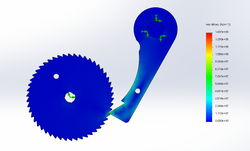
Ratchets and pawls were chosen for the transmission system because of their power saving capabilities. The pawl could hold the ratchet, and therefore the arm, at discrete angles without needed constant torque from the motor - allowing the wearer to save power while not moving their arm. The ratchets and pawls that were chosen were 2" in diameter, had 45 teeth, and face width of 1/2". They were to be water jet out of 1/2" Low Carbon Steel. Running a Finite Element Analysis on the shoulder system (expected to see the largest torque of 14 N-m), showed that the current configuration has a factor of safety of 3. With no significant force present in the pawls shaft or individual ratchet tooth.
 |  | |
|---|---|---|
|
CAM
Another important aspect of the ratchet and pawl system is the cam. The Cam is located between the two coaxial pawls. By rotating the Cam 10 - 45 degrees clockwise, or counter clockwise, a different pawl is engaged changing the allowable direction of the arm joint. The Cam is fabricated in house. The triangular shape of the Cam is intended to give sufficient mas to overcome the force on the pawls, and to minimize the angle and time, required to change which pawl is engaged. The Cam has a 20:3 gear ratio associated with it thanks to the 100 and 15 tooth gears attached to the Cam and Lx-16a servo motor respectively. The gear configuration gears up the torque from 95 lbs/in to 633 lbs/in. With the current configuration, the force that the Cam needs to exert on the pawl is approximately 463 lbs/in, this torque takes the full force of the shoulder joint into account. Additionally, the pawls have a dowel pin through-hole to ensure that that their teeth are misaligned by 1.8 degrees. This misalignment ensures that there is a tooth length for the motor to reverse direction, before catching on the pawl, in either rotational direction. By allowing the motor to make this tooth length reverse shift, the force on the pawl is reduced, allowing the Lx-16a servo motor to turn the Cam. The force of the cam exceeds the needed force to switch the pawl by a factor of 1.37, and it has the purposeful misalignment to reduce the required force preemptively.

BOWDEN CABLES
Albert Tai
Bowden cables are steel cables shielded by wear-resistant plastic sheaths, which were chosen for this project's power transmission system due to their ability to stay under tension regardless of the jacket routing scheme. Thus, bowden cables can move along with the user's arm without fear of cables losing tension.
The cable end for the shoulder joint was mounted as far away from the shoulder pivot point as possible without interfering with the user's range of motion; this distance was determined to be about 7 inches. Such an offset was included so that the cable can apply more torque to the shoulder joint. Cable mounting for the elbow joint required more thought with regards to what configuration would maximize torque applied to the forearm. Those calculations and thoughts can be glimpsed from the diagrams below. But, in the end, the most effective length was determined to be 9 inches.
 |  |  |
|---|---|---|
 |
PULLEY SYSTEM
The Pulleys are the gear ratio aspect for the Transmission System. For the shoulder joint, one 2 inch diameter. pulley was used, and for the elbow joint, two 1 inch diameter pulleys were used. The elbow Transmission System utilizes both a push and pull motion, to move the forearm between 10 degrees and 100 degrees, in flexion and extension (elbow in right angle, or straight). This range was chosen to ensure a safe, but full, range of motion for the user. For the elbow, 0 degrees is defined as when the forearm is in full extension and 90 degrees is counterclockwise from there - in the natural direction that the elbow bends. The shoulder joint utilizes the pull motion to raise the shoulder, and gravity to bring the shoulder back down. Because the elbow can't always rely on gravity to bring it back to 0 degrees, it needs a push and pull functionality while the should does not. The shoulder's 0 degrees is defined as when the forearm is at the wearers side, and 90 is is counterclockwise from there, again in the natural direction that the shoulder moves in. The safe range of motion for the shoulder is 0 degrees to 110 degrees. Taking the force required, applied and cable mounting distances, the final pully diameters were determined. Based on the chosen ratchets, with 45 teeth, the shoulder can move in 2 degree discrete increments and the elbow in 1 degree increments.
